I have been working on this project for a while and whilst it is still under development here’s a short guide after several requests to do so. The dimmer uses an interrupt driven XL-Maxsonar EZ1 ultrasound range finder to measure the distance between the sensor and your hand. By moving your hand up and down over the sensor you can increase or decrease the amount of light emitted by the connected halogen lamp.
In this post I will explain how one can make the basic dimmer based on a simplified circuit. This dimmer later evolved to include an LCD, SHT15 temperature and humidity sensor, DS1307 realtime clock and a mosfet driver to drive the mosfet above 30Khz so the unpleasant dimmer humming noise would disappear. I will talk more about this later.
First things first, here’s a movie of the latest version of the dimmer in action, it includes an LCD, a temperature and humidity sensor, a realtime clock and an alarm function that simulates a sunrise:
[youtube width=”590″ height=”420″]http://www.youtube.com/watch?v=NGR54NZKIrM[/youtube]
Dimmer Circuit
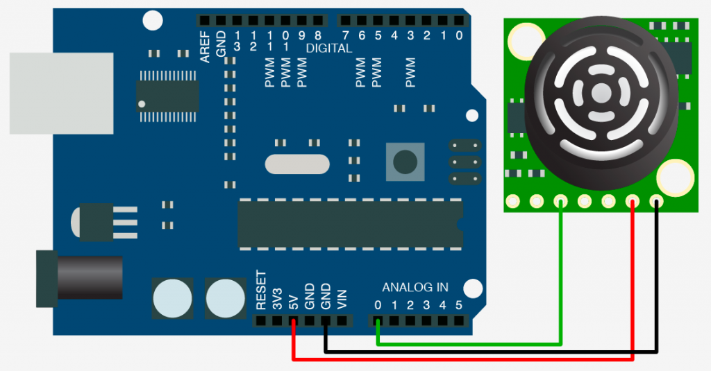
To build this dimmer one should first connect the Ultrasound Sensor to the Arduino and make sure one can get reliable data from it:
Further one should use a capacitor to smooth out the power supply to the sensor. I found that this results in much less noise in the readings from the sensor and is thus a must.
The Dimmer circuit uses an optocoupler to decouple the power supply of the halogen lamp from the Arduino. Whilst this is not necessary it is certainly good practice and might save your Arduino in case something goes wrong:
Once the sensor and the halogen lamp is wired up as shown in the above diagrams the basic version of the dimmer is finished. You should now be able to use the code at the bottom of the page to get your dimmer working.
Humming Dimmer
One of the biggest issues for me at the beginning of this project was the high-pitched humming noise that the dimmer circuit would make. Whilst inaudible during the day, I found the noise very unpleasant when reading in the evening. The worst part of it was that when I programmed an alarm function to be awoken by a simulated sunrise it was actually the high pitched noise that got me out of bed rather than a gentle virtual sunrise….
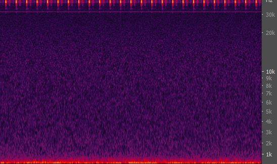
So I went ahead and recorded the sound my circuit was making with an Edirol recorder.A spectrum analysis of the recording nicely shows that in certain frequency bands we had a constant noise. Below is the recording at the standard Arduino PWM rate of 488Hz.
Whilst this may look like random noise changing the pwm frequency to 3900Hz yielded a much clearer picture.
It became evident that the frequencies of the humming noise where exact multiples of the pwm frequency. Based on these results the goal was to increase the PWM frequency of the Arduino above the human hearing range which is roughly 15-
Ultrasonic Dimmer Code
Below is the a simplified version of my code, excluding the SHT15 temperature and humidity sensor code , real-time clock code, LCD code and wake up alarm code:
// Ultrasonic Dimmer v2.3
// Thanks to glacialwanderer for his tutorial on the Max range finder and to Paul Badger for his autoscale function

int max_ez1_an_pin = 2;// it must be digital pin 2 or 3 for the interrupt to work
int LED_pin =9 ;
int LAMP_pin = 3;

int max_ezl_an_pin_status = 0;

volatile unsigned long time_sonar_pin_went_high_us;
volatile unsigned long time_sonar_pin_went_low_us;
volatile long time_sonar_pin_difference_us;
volatile long time_sonar_pin_reference_us;
volatile boolean pulse_received = 0;

float scaledResult;
int brightness_skew_factor = 0;

//*******************************START_TIMER_VARIABLES***************
unsigned long start_time = 0;
int no_of_loops = 10;
//*******************************END_TIMER_VARIABLES*****************
//*******************************START_GET_DISTANCE_VARIABLES********

int direction_change_filrter_min = 2; // how many readings have to be in opposite direciton for the change to be recognized?
int direction_change_filter_current = 0;
long previous_change_in_distance_us;

long max_change_in_distance_filter_cm = 30; // between readings, the max change is x cm
long max_change_in_distance_filter_us = max_change_in_distance_filter_cm*147/2.54;

long max_range_cm = 130; //maximum range to be considered by the sensor
long max_range_us = max_range_cm*147/2.54;
long start_distance_us;
long current_distance_us;
long change_in_distance_us;
long change_in_distance_percent;
int object_in_range = 0;

boolean change_to_process = 0;

//*******************************END_GET_DISTANCE_VARIABLES***********
//*******************************START_RELEVANT_CHANGE_VARIABLES******

long relevant_movement_range_cm = 40; // how many cm + or - of movement should equal a 100%

long relevant_movement_range_us = relevant_movement_range_cm*147/2.54;
long relevant_relative_percentual_change; // percentual change in relation to movement range

//*******************************END_RELEVANT_CHANGE_VARIABLES********
//*******************************START_Dimmer_variables***************

int fade_delay = 20;

int absolute_brightness_pwm = 0;
int adjusted_brightness_pwm = 0;

// we don't percieve delta in brightness linear, so we got to account for that
//*******************************END_Dimmer_Variables*****************

void setup()
{
Serial.begin(9600);
pinMode(max_ez1_an_pin, INPUT);
pinMode(LED_pin, OUTPUT);
pinMode(LAMP_pin, OUTPUT);
attachInterrupt(0, interupt_get_sonar_time, CHANGE); // 0 here equals digital pin 2

TCCR1B = TCCR1B & 0b11111000 ¦ 0x03;
/*
Pins 9 and 10: controlled by timer 1, pwm frequency modification...

Setting Divisor Frequency
0x01 1 31250
0x02 8 3906.25
0x03 64 488.28125
0x04 256 122.0703125
0x05 1024 30.517578125

TCCR1B = TCCR1B & 0b11111000 ¦ ;
*/
}

void interupt_get_sonar_time()
{
if (digitalRead(max_ez1_an_pin) == HIGH) // if pin is high and was low before
{
time_sonar_pin_went_high_us = micros();
}
else if (digitalRead(max_ez1_an_pin) == LOW) //if the pin is low and was high before
{
time_sonar_pin_went_low_us = micros();
time_sonar_pin_difference_us = time_sonar_pin_went_low_us-time_sonar_pin_went_high_us;
pulse_received = 1; // one that is different from before, so a change, thats all we are interested in
}
}

void loop()
{
//start_time =micros();
//for(int i=0;i<no_of_loops;++i) {
if (pulse_received == 1)
{
current_distance_us = int (time_sonar_pin_difference_us);
if(object_in_range == 0 && current_distance_us < max_range_us) //if we didn't have an object in range but do so now
{
start_distance_us = current_distance_us;
change_in_distance_us = 0;
object_in_range = 1; // got now an object in range
}
else if (object_in_range == 1 && current_distance_us < max_range_us)
{
//we still have something in range, so will check if it moved
previous_change_in_distance_us = current_distance_us-start_distance_us;
// START direciton change filter
if ( change_in_distance_us < 0 && previous_change_in_distance_us > 0 && direction_change_filter_current <= direction_change_filrter_min) // change in direction one { change_in_distance_us = 0; direction_change_filter_current = direction_change_filter_current + 1; } else if ( change_in_distance_us > 0 && previous_change_in_distance_us < 0 && direction_change_filter_current <= direction_change_filrter_min) //change in direction two
{
change_in_distance_us = 0;
direction_change_filter_current = direction_change_filter_current + 1;
}
else
{
direction_change_filter_current = 0;
change_in_distance_us = previous_change_in_distance_us;
start_distance_us = current_distance_us;
}
// END direciton change filter
change_to_process = 1;
}
else
{
object_in_range = 0; //lost track of our object, restart routing
change_in_distance_us = 0;
}
pulse_received = 0; // as the pulse was processed and we are waiting for the next one
}

if (change_to_process == 1 && change_in_distance_us <= max_change_in_distance_filter_us) { relevant_relative_percentual_change = change_in_distance_us*255/relevant_movement_range_us; // compute the new brightness of the lamp absolute_brightness_pwm = absolute_brightness_pwm + relevant_relative_percentual_change; if(absolute_brightness_pwm > 200)
// 200 and not 255 so we can see with our eyes when we are at full brightness, otherwise the change is too subtle
{

analogWrite(LED_pin, 255);
analogWrite(LAMP_pin, 255);
if (absolute_brightness_pwm > 255)
{
absolute_brightness_pwm = 255;
}

}
else if(absolute_brightness_pwm <= 0) { absolute_brightness_pwm = 0; analogWrite(LED_pin, absolute_brightness_pwm); analogWrite(LAMP_pin, absolute_brightness_pwm); } else { float scaledResult = (fscale( 0, 200, 0, 200, absolute_brightness_pwm, brightness_skew_factor)); adjusted_brightness_pwm = int(scaledResult); analogWrite(LED_pin, adjusted_brightness_pwm); analogWrite(LAMP_pin, absolute_brightness_pwm); } change_to_process = 0; } else if(change_to_process == 1) //change esceeded max change in distance, wont process change, start over { change_to_process = 0; } serial_debug(); //} //Serial.print(micros()-start_time); //Serial.print(" microseconds for "); //Serial.print(no_of_loops); //Serial.print(" loops, last median range value was; "); //Serial.println(current_distance_us*2.54/147); } void serial_debug() { Serial.print("Current distance: "); Serial.print(current_distance_us*2.54/147); Serial.print("cm, Delta distance: "); Serial.print(change_in_distance_us); Serial.print(" uS, "); Serial.print(change_in_distance_us*2.54/147); Serial.print(" cm, RR % change: "); Serial.print(relevant_relative_percentual_change); Serial.print(" %, Brightness percentage:"); Serial.print(absolute_brightness_pwm); Serial.print(" %, Adj. pwm; "); Serial.print(adjusted_brightness_pwm); Serial.println(" / 255"); } float fscale( float originalMin, float originalMax, float newBegin, float newEnd, float inputValue, float curve) // thanks to Paul Badger 2007 { float OriginalRange = 0; float NewRange = 0; float zeroRefCurVal = 0; float normalizedCurVal = 0; float rangedValue = 0; boolean invFlag = 0; if (curve > 10) curve = 10;
if (curve < -10) curve = -10;
curve = (curve * -.1) ;
curve = pow(10, curve);
if (inputValue < originalMin) { inputValue = originalMin; } if (inputValue > originalMax) {
inputValue = originalMax;
}
OriginalRange = originalMax - originalMin;
if (newEnd > newBegin){
NewRange = newEnd - newBegin;
}
else
{
NewRange = newBegin - newEnd;
invFlag = 1;
}
zeroRefCurVal = inputValue - originalMin;
normalizedCurVal = zeroRefCurVal / OriginalRange;
if (originalMin > originalMax ) {
return 0;
}
if (invFlag == 0){
rangedValue = (pow(normalizedCurVal, curve) * NewRange) + newBegin;
}
else
{
rangedValue = newBegin - (pow(normalizedCurVal, curve) * NewRange);
}
return rangedValue;
}


An intelligent answer – no BS – which makes a pelaasnt change
Nice job. Cool project.
Super Cool…Keep writing…it’s hot.
Nice project. I came across this while googling for Halogen-Dimming circuits with arduino as I also want to build a sunrise lamp.
Would you mind sharing what MOSFET driver chip you ended up using ?
I used a TC4420 Mosfetdriver from Microchip.
Hello, i think that i saw you visited my website so i came to “return the favor”.I’m attempting to find things to improve my web site!I suppose its ok to use some of your ideas!!\
Hey great project! I like that you took the time to account for the inability to discern change in brightness linearly. I would like to try your project but only have the HC-SR04 ultrasonic sensor, how would I change the code to use this sensor? Also, why do you light an LED the same way you light the Lamp? Just as a check if the lamp fails? Thanks 🙂
You’re correct, the LED was just to check if everything is working. When I build the circuit, most of the time I didn’t have a Lamp connected. All you would really have to change is the sensor reading part but it seems it also just sends the pin high and you have to measure that duration. So without looking into too much detail, doesn’t the code work the way it is for your sensor?
We own a cat, and I’m afraid this will make an efficient cat-repelling device when generating sound at 31 Khz, because cat can hear up to 64 khz (dogs up to 60khz). How can I drive the frequency up even further? Could you adopt your schematics so that it will show the MOSFET driver, preferably operating at a higher frequency?
You can use pin 5 or 6 and set it to 62.5 khz, that will do the trick.
http://playground.arduino.cc/Main/TimerPWMCheatsheet
The hum in general is of very low amplitude. Just like most humans don’t notice it, I doubt most animals do even if it is within their hearing range.
I don’t have the schematics anymore so I can’t modify it quickly. However, this should give you a good idea on how to connect it:
https://www.quora.com/What-is-the-purpose-of-a-MOSFET-gate-driver
Cheers,
Adrian
Pingback: Ultrasonic Dimmer -Use Arduino for Projects